The Power of Safety Interlocks in Heat Transfer Systems
Safety interlocks in a heat transfer system are key to preventing potential damage, and therefore ensuring overall system integrity. Safety interlocks act as vigilant guardians, continuously monitoring the critical parameters of your process and responding to any deviations from normal operating conditions. When integrated properly, they promptly identify and address the dangers they are set up to protect against.
HEAT tests the functionality of all the interlocks on our systems before they leave our factory doors, as they are critical to your safety.

Safety interlocks help to:
- Prevent Equipment Damage: Safety interlocks safeguard sensitive components, such as heating elements and thermal fluid, from damage caused by factors like low flow, overheating, or excessive pressure.
- Extend System Lifespan: By averting conditions that could lead to wear and tear or catastrophic failures, safety interlocks contribute to the prolonged life and reliability of the heat transfer system.
- Ensure Process Efficiency: Continuous monitoring and intervention by safety interlocks maintain the system's efficiency, preventing disruptions that could impact the overall performance of the heat transfer process.
- Facilitate Predictive Maintenance: Safety interlocks provide early warnings of potential issues, enabling operators to schedule preventive maintenance activities and address concerns before they escalate.
- Enhance Operational Safety: The inclusion of safety interlocks establishes a proactive safety framework, reducing the risk of accidents or malfunctions that could compromise the safety of personnel and the surrounding environment.
- Meet Codes & Engineering Best Practices: While safety interlocks have costs, the costs of cutting them out can be far greater should something go wrong.
- Help Reduce Insurance Costs: Insurance costs are typically considered through risk assessments. Safety interlocks help reduce the risk of failure and safety to the operator and as a result help reduce the insurance cost of the equipment, line, operation, personnel, and overall plant.
In essence, the main benefit of including safety interlocks in your heat transfer system is to make it safe & reliable with minimized risk of unexpected failures or damages. The safeguards that interlocks provide play a crucial role in protecting both the components within the system itself, the overall process the heat transfer system is connected to, and most importantly the workers that interact with the system.
Common Safety Interlocks
Safety interlocks in a heat transfer system monitor the health of the system by measuring 4 things: Temperature, Flow, Level, and Pressure.
TEMPERATURE
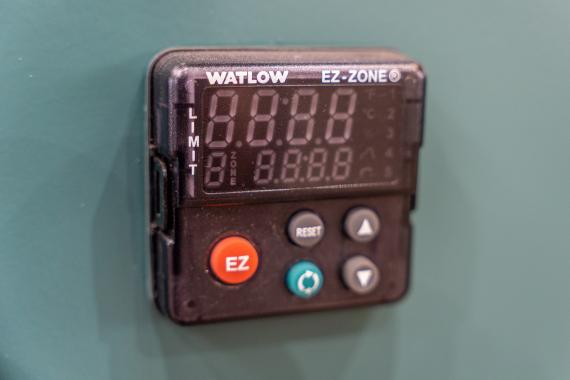
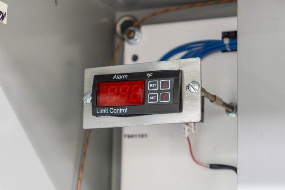
- Interlock Device: Over-Temperature Limit Switch
- Purpose: Preventing heating element surface temperatures from becoming dangerously hot.
- Protection Against: Damage to heating elements and thermal fluid due to excessive temperatures.
- Installation: Sensors are located inside the flanged heater, directly measuring the sheath temperature of the element. These sensors are wired back to the control panel where the high temperature switches are located.
All our systems are equipped with an over-temperature sensor placed within the flanged heater element bundle. This sensor is located inside a thermowell that ends on the surface of one of the heater elements, directly measuring the sheath temperature of the element. If the sheath temperature gets too high, the limit switch will activate and interrupt the power to the heater circuit.
The sheath temperature is often higher than the bulk temperature of the fluid, and the location of the thermowell here avoids inaccurate readings. As a result, the limit switch prevents damage caused by overheating to both the heating elements and thermal fluid.
FLOW
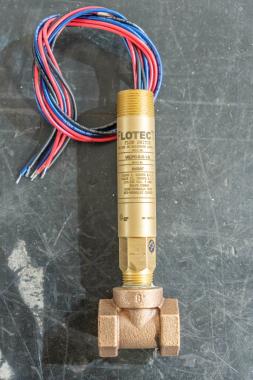
- Interlock Devices: Flow Switch, Pressure Switch, Differential Pressure Switch
- Purpose: Ensures a minimum fluid flow through the system. Offers insights into flow rate and detecting issues like blockages.
- Protection Against: Damage to heating elements and heat transfer fluid due to insufficient flow.
- Installation: Strategically positioned in the main flow path.
Flow Switches are used to prevent the system or portion of the system from operating if there is less than a minimum flow or no fluid flow through the system. This helps to protect the heating elements of the system, which can be damaged if there is insufficient or no flow; without flow to pull heat away from the heater elements, surface temperature builds at the film level and can cause irreversible damage to both the heater and fluid.
Pressure Switches and Differential Pressure Switches can measure the internal pressure of the system at various points, also allowing the system to monitor pressurization or flow. If the measured pressure is too low, it can be an indication that the flow rate is below the desired value. These switches are set up so that the heater and/or the heater & pump will shut off if an anomoly is detected, allowing the issue to be diagnosed and repaired before causing damage.
These switches also protect against damaging the thermal fluid - without flow, the fluid in the heater chamber is continually heated, possibly allowing the fluid to reach temperatures beyond its maximum bulk temperature. When this happens, the fluid begins to break down and carbonize, or even to auto-ignite. The fluid may break down so much that it needs to be filtered or entirely replaced. This carbonization can also begin to cause a layer of coke to build up on the heater's elements, which then can insulate the element and damage it even further.
LEVEL
- Interlock Device: Low Level Switch
- Purpose: Guards against insufficient fluid levels.
- Protection Against: Pump cavatation or failure caused by running dry.
- Installation: Placed in the expansion tank.
This switch is placed in the expansion tank, ensuring that the system never reaches a point where there is not enough fluid in the system or the net positive suction head rate (NPSHr) for the pump isn't met. If the low-level switch is tripped, this is usually an indication that there is a leak somewhere along the line. If the fluid were to continue to escape the loop of the process, it would lead to permanent damage of the pump (by running dry) and heater (by heating fluid with no flow across the elements or even while exposed to air).
HEAT interlocks the low-level switch with the pump and heater - if the switch isn't satisfied, the pump will shut off and the heater will be de-energized until the fluid level is restored.
PRESSURE
- Interlock Device: Pressure Relief Valve
- Purpose: Disperses excessive pressure to protect the weakest point of process and equipment.
- Protection Against: Pressure build-up that could lead to damage or catastrophic failure.
- Installation: In the system piping or on a pressure vessel, positioned for safe relief of the over-pressurized fluid.
Relief valves are used to disperse pressure from the process when it gets too high, protecting both the process itself and any equipment in the system. These valves usually balance the internal pressure with a spring force within the valve. This spring force can be adjusted to a variety of different values depending on your needs. When the process pressure gets too high, the force exerted on the spring becomes greater than the force that is balancing it, causing the spring to compress and opens the valve. This allows the pressure to be dispersed, preventing damage.
Relief valves can operate as pressure control and as a complete fail-safe. They can also be sized for various conditions such as full-flow relief, thermal expansion, and can be fire-sized. Relief valves open fully as soon as a set pressure (+/-10%) is reached, completely relieving the pressure within the system. Once a relief valve “pops” it is recommended that these valves be reset before further use of the system.
What do I do if my Safety Interlocks are triggering?
If your safety interlocks are triggering, it indicates that there's a deviation from normal operating conditions, and immediate attention is required to ensure the safety and integrity of the heat transfer system.

Here's a general guide on what to do next:
- Stop Operations:
As soon as a safety interlock is triggered, stop all operations associated with the affected part of the system. This helps prevent further damage and ensures the safety of personnel.
- Identify the Root Cause:
Investigate the root cause of the triggered interlock. Examine system parameters, fluid levels, temperatures, pressures, and other relevant factors to identify anomalies or malfunctions.
- Refer to System Documentation:
Consult the system documentation, including manuals and schematics, to understand the normal operating conditions and the purpose of the triggered interlock. This can provide valuable insights into the potential issues.
- Address Immediate Hazards:
If the triggering of the safety interlock poses an immediate hazard (e.g., high temperatures or pressures), take steps to address these hazards promptly. This may involve shutting down relevant equipment or isolating specific sections of the system.
- Perform Visual Inspection:
Conduct a visual inspection of the system components associated with the triggered interlock. Look for leaks, damaged equipment, or any visible signs of malfunction.
- Check Sensors and Instruments:
Inspect sensors, instruments, and control devices related to the triggered interlock. Ensure that these components are functioning correctly and are calibrated within specified parameters.
- Consult System Experts:
If you're unable to identify or rectify the issue, consult with our Service Team, engineers, or maintenance personnel who are familiar with the heat transfer system. They can provide valuable insights and assistance.
- Reset and Resume Operations:
After addressing the identified issues and ensuring that the system is in a safe condition, reset the safety interlock as per the system guidelines. Resume operations cautiously, monitoring the system closely for any signs of recurring issues.
- Document and Report:
Document the details of the triggered interlock, the actions taken, and the resolution. Report the incident to relevant personnel or management as part of the system's maintenance and incident reporting procedures.
- Schedule Preventive Maintenance:
Use the information gathered from the incident to schedule preventive maintenance activities, such as fluid sampling and filtration. This helps address underlying issues and prevents similar incidents in the future.

Always prioritize safety, and if in doubt, consult with our qualified professionals for guidance. Regular training for system operators on response protocols for triggered safety interlocks is also essential. Remember – your safety relies on YOU. If you’re unsure about what happened, HEAT’s Service Team will be happy to help.


